Selecting Inputs: the Bubble Concept
In the Generate Node Type dialog, in the Input Properties section, click Select from Model.
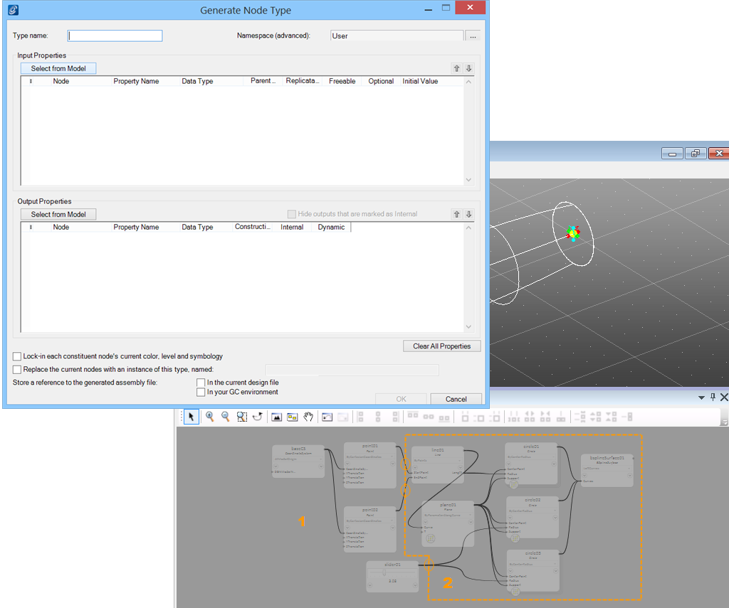
Select the inputs of the future node in the Graph or Geometry window. In the example below, only point01 and point02 are selected as inputs. Remember, if you draw an imaginary bubble around all nodes that should become part of the new node, all the lines that cross that boundary indicate to the inputs you will need to create the node in the future. Selecting one of them is usually enough for GenerativeComponents to detect and highlight the others as well. Notice that in our example below, circle02 and circle03 are dependent on the slider, thus the slider is also automatically selected as an input.
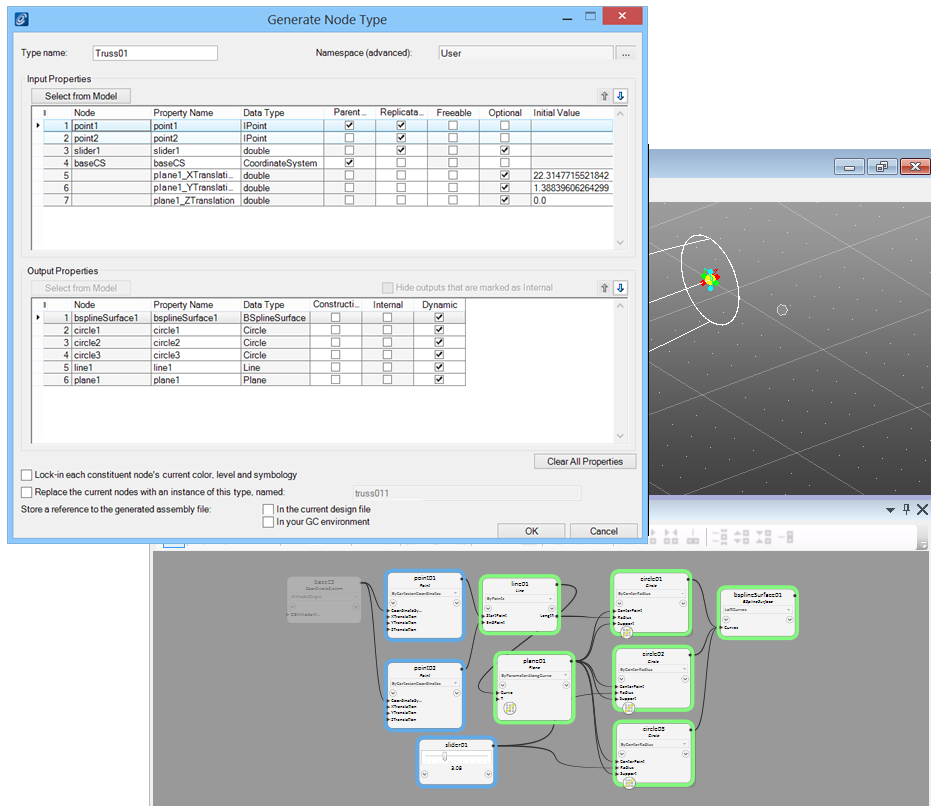
Once the inputs have been selected, the existing node icons in the Graph are highlighted with colors to indicate the inputs and outputs as diagrammed in the bubble concept above. A blue outlined node represents an input, while green represents an output . If a node is outlined in blue and green, it has not been explicitly selected but is an inferred input based on the initial selection.
Clicking Select From Model under the Input Properties dialog starts the selection of input nodes. In most cases it is not necessary to select the outputs because they are automatically selected based on the input selection.